MDPO Dynamic System Function Summary
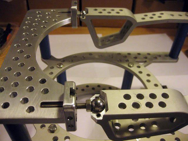
The dynamic system has 4 main components that allow the desired range of motion and adjustment to position.
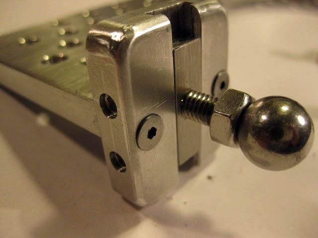
The connecting plate is the base where the universal hinge ball is mounted.
The hinge joint of each arch is mounted on this ball.
The arch then has the dynamic ball joint mounted to the opposite end.
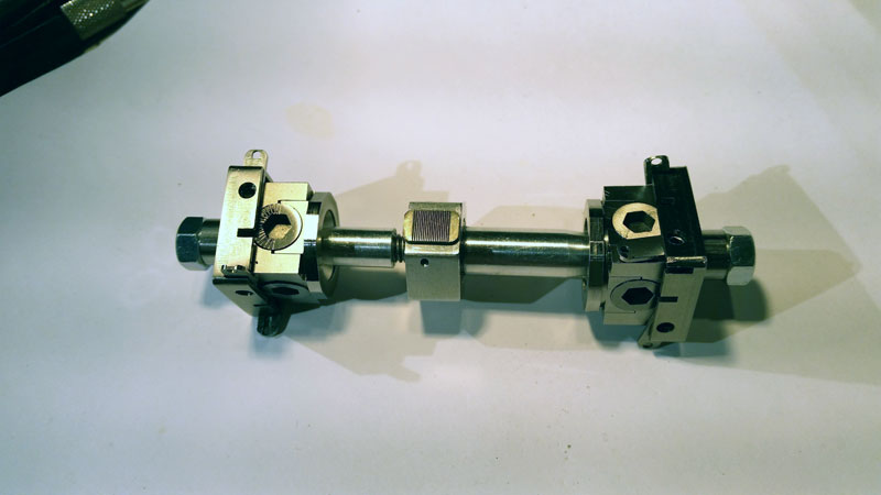
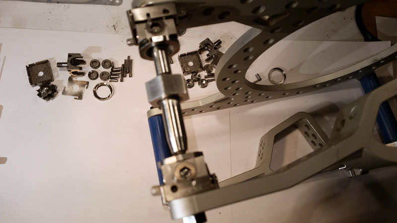
The dynamic ball joint is connected to the upper ring dynamic ball joint with the dynamic Column.
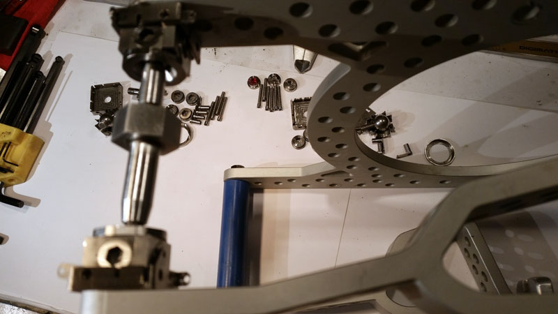
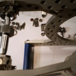
 MDPO Dynamic Arch Assembly
 MDPO Dynamic Connecting Plate  Dynamic Ball Joint
|
 MDPO Dynamic Arch Assembly
|


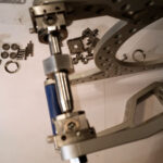
MDPO Dynamic Column
Components of the MDPO Dynamic System
- Connecting Plate
- The new Connecting Plate mounts the vertical slide for the hinge ball. The vertical is locked by screws on the side. The length is locked with hex nuts.
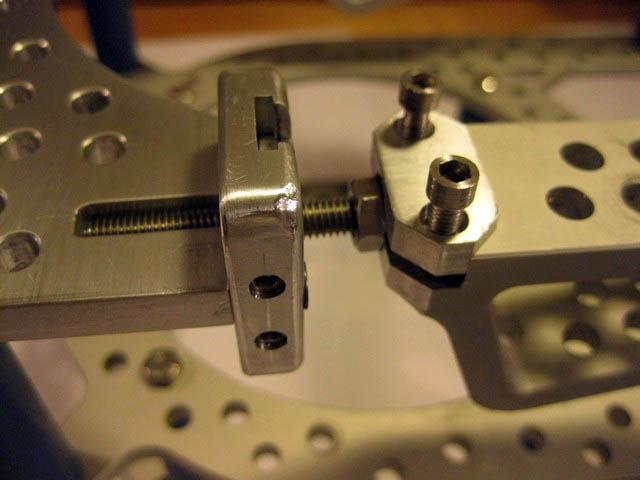
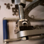
- Dynamic Hinge
- Dynamic Hinge allows the arches to swivel in any direction. The hinge can also move in elevation. It is constrained by the Dynamic Column and Ball Joint Assembly on the tip of each arch.
-
- Dynamic Hinge allows the arches to swivel in any direction. The hinge can also move in elevation. It is constrained by the Dynamic Column and Ball Joint Assembly on the tip of each arch.
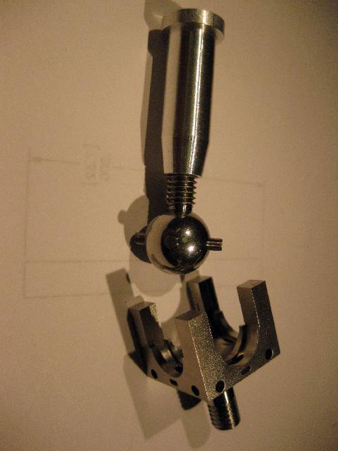
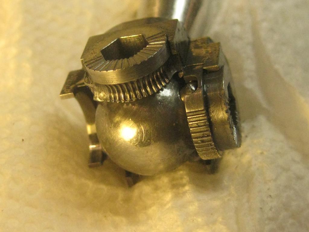
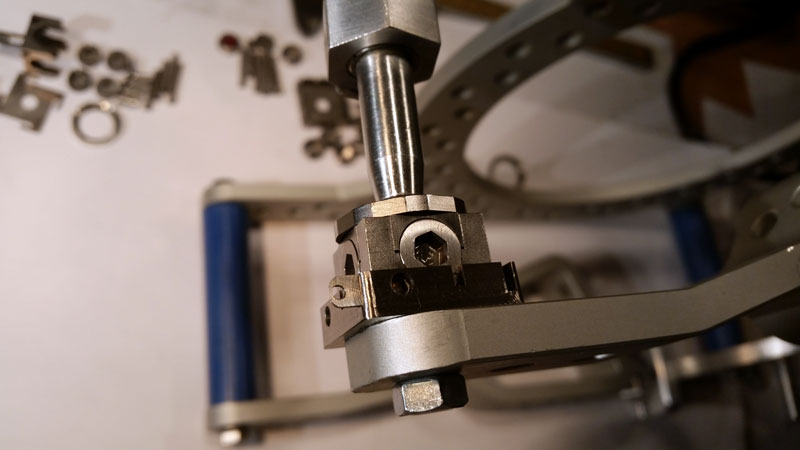
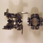
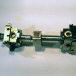
- Dynamic Ball Joint
- The Dynamic Ball Joint consists of a sphere with 2 crossing axis that are perpendicular to the threaded mount where the Dynamic Column is threaded on.. This takes the form of 4 Dowel pins that intersect the 4 adjustment knobs in a pocket in each knob that is off center and acting as a cam to manipulate the ends of the axis that pass through the center sphere. By rotating the adjustment knobs the vertical angle of the column can be modified to any angle in any direction up to 45 degrees. The Levers rotate worm gears to engage the adjustment knobs and act as a lock and fine adjustment to the column angle. The hole passing through the adjustment lever is eccentric to the diameter of the lever. This acts as a cam and engages the worm and drive gears when the lever is rotated 90 degrees.
-

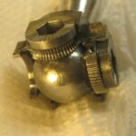
- Ball and axis pins
-
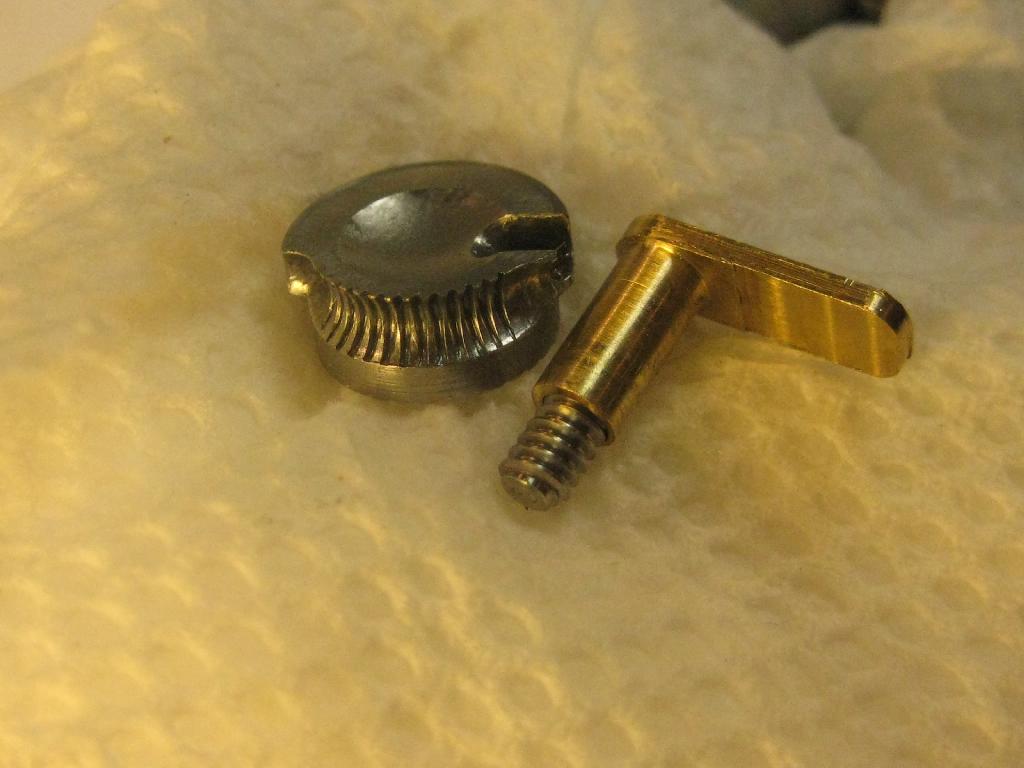
- Adjustment Knobs and Locking Levers
-
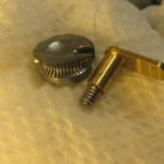
- Lever and Worm Gear
-
- Adjustment Knobs
-
- The Dynamic Ball Joint consists of a sphere with 2 crossing axis that are perpendicular to the threaded mount where the Dynamic Column is threaded on.. This takes the form of 4 Dowel pins that intersect the 4 adjustment knobs in a pocket in each knob that is off center and acting as a cam to manipulate the ends of the axis that pass through the center sphere. By rotating the adjustment knobs the vertical angle of the column can be modified to any angle in any direction up to 45 degrees. The Levers rotate worm gears to engage the adjustment knobs and act as a lock and fine adjustment to the column angle. The hole passing through the adjustment lever is eccentric to the diameter of the lever. This acts as a cam and engages the worm and drive gears when the lever is rotated 90 degrees.
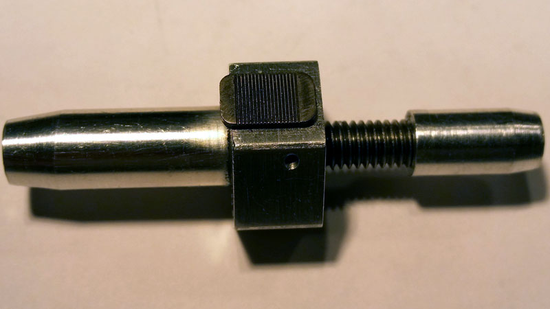
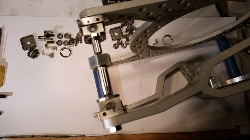
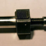
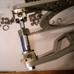
- Dynamic Column
- The Dynamic Column is used to expand and contract the length or distance between the arches and the rings.
-
- Dynamic Column
-
- MDPO Dynamic Column
-
- MDPO Dynamic Column
-
- MDPO Dynamic Column
-
- MDPO Dynamic Column
-
- MDPO Dynamic Column
-
- The Dynamic Column is used to expand and contract the length or distance between the arches and the rings.